Well, that was quite a bit of wait between updates, but lighting is done. Sort of.
It's helpful for me to see what I need to do to flesh the shaders out. Later on I'll need to add textures, and shadows, and multiple sources of light. The nice thing about space shooters, though, is that you generally only have one big source of light to worry about. Certainly, there is plenty of room for lighting effects all over, but what's going to be illuminating the planets, asteroids and ships for the most part is the big star in the middle.
A concern I'm having is that as I add features, the code is getting a more unwieldy. For the most part I've avoided a serious case of spaghetification, but I really should spend some time consolidating certain pieces of code. Before I do that, however, I want to have a better feel for what works and what doesn't in my design.
I've already identified some decisions that weren't the best. For example, my use of inheritance would in many cases be better suited to templates. I wanted to avoid templates, because they are somewhat arcane in their workings, but already my use of the standard and boost libraries has me working with them. I feel more confident now about using them, and it would simplify some things.
This means I'm going to have to do a bit of a rewrite of several big chunks. Rewrites aren't fun, but on the positive side I'm not going to be starting from zero. That seems like a good opportunity to reassess and redesign, so I want to get a bit more experience in before I undertake that particular task. It's a fragile balance I have to manage between having enough features in there that I know how to design it better and having so much that redesigning it is too daunting to do.
It doesn't help that work has picked up and I'm generally too burned out to focus on this when I get home. That's also part of why I've let the update schedule slip, for which I apologize.
In the interest of making things easier for everyone, I've switched back from 7z to zip files to share the program. 7z was a necessity when I was sharing the program through gmail. Mail programs don't like zipped executable files, and having people rename a file from .jpg to .exe to get around it was more trouble than convincing them to use 7zip. But with the files now hosted in Google Docs, I can go use zip files again.
As always, the folder is Framework Releases, and the project itself is Framework-0.0.8.
Showing posts with label Demo. Show all posts
Showing posts with label Demo. Show all posts
Monday, November 7, 2011


Monday, October 10, 2011
Collision Detection - Part 3 - Space Partitioning
In the previous two parts I walked through my own implementation of collision detection and resolution, a pretty basic one at that. You can find a working demo of everything I described here: Framework-0.0.7.
As I was saying last time, however, this method of comparing everything to everything has a problem. The number of collision tests required grows with the square of the number of items. This severly limits the number of elements that can fit in a scene. It should not be too noticeable in the demo, but once I add better shaders. more complex models and more game logic it all starts adding up.
It's also just plain wasteful to check things we know can't collide. The question lies in how to make the computer aware of this. That's where space partitioning comes in.
Consider a surface with a set of scattered circles. My current method would have me compare every object to every object. For the case of say, fifty circles, that would require 1,225 checks. However, we know that the objects on the far sides of the surface can't possibly touch each other. So we split the surface in two, so that each half contains twenty-five objects, and run the collision detection on each half independently.
Using the formula from before, (n-1)*n/2, we determine that each half now requires 300 checks, for a total of 600 checks for both sides. With just splitting the space once, we've halved the required number of checks. We can go further, of course. If we split the space in four, leaving thirteen objects in each quarter(rounding up), we will require 78 checks per quarter. A total of 312 checks.
Split the space again, into eights, so that each contains seven elements. The required number of checks is then 21 per partition, or 168 total. How low can we go? Let's say we split the space in 32 areas, each with 2 elements. We only need one check to make sure two objects aren't touching. The total would then be 32 checks. That's a considerable decrease from the original scenario, about a fortieth of the number of required checks.
The goal, then would seem to be to split the space until we have as few elements in each area as possible. However, for this example, I took the liberty of assuming the circles were all uniformly distributed, and would fill all the areas without leaving gaps. In reality, as they move and bounce about, the density of circles in a given area will change unpredictably. If we draw a fixed grid, there's no way to guarantee that they won't all find their way into the same spot.
We could try making the grid very fine, to limit the likelyhood of many elements occupying one at once, but that means that we have a great number of areas, many of which may well be empty. We have to go through each and every cell to check how many objects it has, so we want to avoid empty cells as much as posible, since they add to our overhead. Furthermore, if the cells are very small, the likelyhood of a single circle occupying several cells increases. For a given grid, a circle could fit in between one and four cells, provided the cells are as large as the circle.
There is an additional overhead that space partitioning brings, in that you have to keep the grid updated. It's easy enough to determine what grid an object belongs to, but we want to traverse the grid, not the object list. That means that each time an object moves, we need to keep track of wether or not it changed cells. We can at least get rid of empty cells, and avoid checking cells with just one element.
There is a way to avoid some of the problems with grids, however, through the use of structures called quadtrees (in 2D) and their extension in 3D, octrees. These are complex enough to require a post of their own. The important thing is that we can see how, through the use of space partitioning, we can cut down the time consuming issue of collision detection into something more manageable.
As I was saying last time, however, this method of comparing everything to everything has a problem. The number of collision tests required grows with the square of the number of items. This severly limits the number of elements that can fit in a scene. It should not be too noticeable in the demo, but once I add better shaders. more complex models and more game logic it all starts adding up.
It's also just plain wasteful to check things we know can't collide. The question lies in how to make the computer aware of this. That's where space partitioning comes in.
Consider a surface with a set of scattered circles. My current method would have me compare every object to every object. For the case of say, fifty circles, that would require 1,225 checks. However, we know that the objects on the far sides of the surface can't possibly touch each other. So we split the surface in two, so that each half contains twenty-five objects, and run the collision detection on each half independently.
 |
| Each line represents one required pairwise check. Doubling from three to six elements increased the required checks five times, from three to fifteen. |
Split the space again, into eights, so that each contains seven elements. The required number of checks is then 21 per partition, or 168 total. How low can we go? Let's say we split the space in 32 areas, each with 2 elements. We only need one check to make sure two objects aren't touching. The total would then be 32 checks. That's a considerable decrease from the original scenario, about a fortieth of the number of required checks.
The goal, then would seem to be to split the space until we have as few elements in each area as possible. However, for this example, I took the liberty of assuming the circles were all uniformly distributed, and would fill all the areas without leaving gaps. In reality, as they move and bounce about, the density of circles in a given area will change unpredictably. If we draw a fixed grid, there's no way to guarantee that they won't all find their way into the same spot.
We could try making the grid very fine, to limit the likelyhood of many elements occupying one at once, but that means that we have a great number of areas, many of which may well be empty. We have to go through each and every cell to check how many objects it has, so we want to avoid empty cells as much as posible, since they add to our overhead. Furthermore, if the cells are very small, the likelyhood of a single circle occupying several cells increases. For a given grid, a circle could fit in between one and four cells, provided the cells are as large as the circle.
There is an additional overhead that space partitioning brings, in that you have to keep the grid updated. It's easy enough to determine what grid an object belongs to, but we want to traverse the grid, not the object list. That means that each time an object moves, we need to keep track of wether or not it changed cells. We can at least get rid of empty cells, and avoid checking cells with just one element.
There is a way to avoid some of the problems with grids, however, through the use of structures called quadtrees (in 2D) and their extension in 3D, octrees. These are complex enough to require a post of their own. The important thing is that we can see how, through the use of space partitioning, we can cut down the time consuming issue of collision detection into something more manageable.
Monday, September 12, 2011
It's full of stars!
I've gotten a few new features into the framework, such as a first implementation on 'shooting', but that's not what I want to talk about today.
So far, I've focused solely on functional details. Making models, making sure the models are displayed, movement, views and such. The result is... well, it's functional. Of course I want to have something good before I start polishing. A polished turd is still a turd, so I have to turn it into something else first.
The traditional way of making a background is making use of a skybox. This is basically a cube you draw around the scene. With the aid of something called cubemapping, you can slap the sky on the inside and the textures used fool the eye into thinking it's looking at a dome, rather than a cube. No seams or anything, if done correctly.
Of course, I didn't have the textures to make it look good handy.while there are plenty of images of space around, there's very few of a look at the complete sky, and those that are have fish eye effects. I could have slapped a few images, merged them together or something and called it a day, but I wanted something special.
So, I started a little side project. The idea being, I'd create the background out of a real galaxy I made up on the spot. This would mean create all the stars, jump into an appropriate position inside the galaxy and take pictures of what is visible in each direction. That way I would have the textures I needed for the cube map. I could scale the definition as much as I want, or move to a different spot and have the constelations in the background actually shift properly.
How to do it, though? A galaxy like our milky way has on the order of a hundred billion stars. Can't really draw them one at a time. Instead, my plan is to split the space the galaxy occupies into as many blocks as I can manage, and give it shape with the use of two functions.
One of the functions will give the galaxy a shape. The second will add some higher frequency noise to make it look more interesting.
I will represent the blocks with points, and once I have it all working try to improve the appearance. I really want the GPU to do the heavy lifting here. I can make a shader program that checks the position of each point and assigns it a value for each function, then multiplies them together. But if I tell the GPU to draw a million points one at a time, the overhead on the calls will slow things to a crawl. So what I do instead is make use of instanced drawing.
Instanced drawing means I tell the gpu to draw a singlemodel (in my case, as ingle point) as many times as I want. It's helpful for drawing many identical objects. The result, after setting the color to solid red, is not very impressive:
Of course, drawing several identical points means they get drawn in the same spot. In order to add variation, the gpu gives me an extra variable, an instance id, which I can manipulate for some interesting effects.
For my first test, I'm sending 0x1000 points to the gpu. That's 4096 in decimal, but you'll see why I work in hex in a bit. This means the instance ids range from 0x0 to 0xFFF (4095). What I can do is treat each of the hex digits as a coordinate in one of the axis, x, y and z, and move the point by that amount. So for example, the point 0x123 maps to position (1, 2, 3). I use bit masks and some bitwise arithmetic to work out the positions, which is why I do it this way. Computers, as you know, like binary and powers of 2 better than decimal.
Adding the instance id into the mix then, the result is a cube made of red dots. Not very impressinve right now, but it's a start.
I can play around with color too. For example, if I treat x as Red, y as Green and z as Blue, I get a colorful cube:

Ok, so back to the galaxy. First, I'll give it a proper shape. A cube is hardly the proper shape, so let's ignore points outside of a central sphere. For that, I'll give points further than 1 unit from the center a color of 0.1. There may be a few stragglers around the galaxy, but they're few and far between.

Much better. Now, galaxies tend to be shaped as disks, more than spheres, so we want to squash the sphere as well. What we want is to decrease the intensity with regards to the height from the plane. I'll use y to measure height from the plane, and to avoid the break being so obvious I'll also diminish the intensity along the diskthe farther you are from the center. The result:

Not so bad. Still need to add more features, though. For example, our galaxy has spiral arms. These will require a bit more thinking.
I didn't get quite as far as I meant to, mostly due to Deus Ex. Still, I don't want to leave you without an update so check out Framework-0.0.6r. You can do everything you could do before, and now shoot too! The space key now fires instead of accelerating, you accelerate with Left Shift. Fun* game to play: see how much you can shoot before it starts slowing down the game. TODO: delete the bullets when they're no longer relevant.
I've also made the folder with all the releases public, so anyone can look up the history without digging through the archives. Framework releases.
* It's fun for me, but then I had fun with the first release too.
So far, I've focused solely on functional details. Making models, making sure the models are displayed, movement, views and such. The result is... well, it's functional. Of course I want to have something good before I start polishing. A polished turd is still a turd, so I have to turn it into something else first.
The traditional way of making a background is making use of a skybox. This is basically a cube you draw around the scene. With the aid of something called cubemapping, you can slap the sky on the inside and the textures used fool the eye into thinking it's looking at a dome, rather than a cube. No seams or anything, if done correctly.
Of course, I didn't have the textures to make it look good handy.while there are plenty of images of space around, there's very few of a look at the complete sky, and those that are have fish eye effects. I could have slapped a few images, merged them together or something and called it a day, but I wanted something special.
So, I started a little side project. The idea being, I'd create the background out of a real galaxy I made up on the spot. This would mean create all the stars, jump into an appropriate position inside the galaxy and take pictures of what is visible in each direction. That way I would have the textures I needed for the cube map. I could scale the definition as much as I want, or move to a different spot and have the constelations in the background actually shift properly.
How to do it, though? A galaxy like our milky way has on the order of a hundred billion stars. Can't really draw them one at a time. Instead, my plan is to split the space the galaxy occupies into as many blocks as I can manage, and give it shape with the use of two functions.
One of the functions will give the galaxy a shape. The second will add some higher frequency noise to make it look more interesting.
I will represent the blocks with points, and once I have it all working try to improve the appearance. I really want the GPU to do the heavy lifting here. I can make a shader program that checks the position of each point and assigns it a value for each function, then multiplies them together. But if I tell the GPU to draw a million points one at a time, the overhead on the calls will slow things to a crawl. So what I do instead is make use of instanced drawing.
Instanced drawing means I tell the gpu to draw a singlemodel (in my case, as ingle point) as many times as I want. It's helpful for drawing many identical objects. The result, after setting the color to solid red, is not very impressive:
 |
| 4096 points, all drawn on top of each other. |
For my first test, I'm sending 0x1000 points to the gpu. That's 4096 in decimal, but you'll see why I work in hex in a bit. This means the instance ids range from 0x0 to 0xFFF (4095). What I can do is treat each of the hex digits as a coordinate in one of the axis, x, y and z, and move the point by that amount. So for example, the point 0x123 maps to position (1, 2, 3). I use bit masks and some bitwise arithmetic to work out the positions, which is why I do it this way. Computers, as you know, like binary and powers of 2 better than decimal.
Adding the instance id into the mix then, the result is a cube made of red dots. Not very impressinve right now, but it's a start.
 |
| I'm moving the points a bit, as well, so they appear centered. |

Ok, so back to the galaxy. First, I'll give it a proper shape. A cube is hardly the proper shape, so let's ignore points outside of a central sphere. For that, I'll give points further than 1 unit from the center a color of 0.1. There may be a few stragglers around the galaxy, but they're few and far between.

Much better. Now, galaxies tend to be shaped as disks, more than spheres, so we want to squash the sphere as well. What we want is to decrease the intensity with regards to the height from the plane. I'll use y to measure height from the plane, and to avoid the break being so obvious I'll also diminish the intensity along the diskthe farther you are from the center. The result:

Not so bad. Still need to add more features, though. For example, our galaxy has spiral arms. These will require a bit more thinking.
I didn't get quite as far as I meant to, mostly due to Deus Ex. Still, I don't want to leave you without an update so check out Framework-0.0.6r. You can do everything you could do before, and now shoot too! The space key now fires instead of accelerating, you accelerate with Left Shift. Fun* game to play: see how much you can shoot before it starts slowing down the game. TODO: delete the bullets when they're no longer relevant.
I've also made the folder with all the releases public, so anyone can look up the history without digging through the archives. Framework releases.
* It's fun for me, but then I had fun with the first release too.
Sunday, September 4, 2011
In the driver's seat
So I have a basic implementation of newtonian movement worked out. But we're still controlling an object that eventually flies off into the distance. And once it's out of view, it's pretty unlikely that it will come back. Wouldn't it be nice, though, if we could keep track of it?
Yes, yes it would. So having worked out movement, I focused on the camera. I decided to start with two views. One from the cockpit, which tracks the rotation of the object, and the other the familiar chase camera, looking at the object from behind, and tracking the direction of movement.
The reason I made these decisions is that movement in three dimensions is pretty unintuitive, specially when you remove friction. Most space flight games get around this unintuitiveness by treating space as a giant pool. You can remain buoyant at any spot, but there's a constant friction that slows you down as soon as you stop your engines. This allows people to point themselves in the direction they want to go and fire the engines. Any transversal motion will eventually be slowed enough that they end up reaching their destination with a minimum of effort.
With newtonian physics, however, there's no meaning to the idea of slowing down. Slowing down with respect to what? Speed is wholly relative. Firing your engines in the direction you want to go leads you to shoot around your target. It is madness. I needed a way to recover some of the intuitiveness, without sacrificing the fun of being in space.
The chase cam was my solution. Other games implement a chase view, but they waste it by keeping it aligned with the ship, so you're always watching your ship from behind. This is useful for shooting things, since weapons tend to be aligned with the front of the ship, but not so much for navigation. It's essentially the same as the cockpit view, only from outside the ship.
With my implementation, the player will see the direction they're actually moving in. If they want to head towards something, they have to align their objective with the center of this view. In the meantime, the ship is free to rotate any which way, and accelerating in different directions will shift the view. Ironically, racing games make a better use of the chase view than space flight games. For the most part you sit squarely behind the car, but you can notice when turning hard around corners or drifting that your car will turn while you keep looking in the direction that your car is still going in.
Still, shooting things is important. I can see how it would be quite distressing not to be able to see what you're shooting at, which is what the cockpit view is for. Eventually, helpful GUI elements will minimize the difficulty of getting from A to B when you don't have friction helping you along, but for a start the chase view should help.
Of course, before applying these views I had to populate the space somehow. A view from the cockpit in empty space would look completely static regardless of your movement. I decided to do two things. First, I draw a cube around the ship, which remains in a fixed orientation at all times. This let's you see how your orientation changes, but since you don't move around the cube but sit always in the middle, you can't see your translation. This is how skyboxes work, but since I don't have textures working yet green lines will have to do.
The second is, I actually start using all the infrastructure I'd been talking about before. During initialization I'm make a few different models (a sphere for 'asteroids', a piramid for the player), and store them in the cache. Then I create an entity for the player, and assign it the piramid model.
For the asteroids I do a little trick to get more variation. Based on the sphere model, I create new models which point to the same vertex buffers (where the sphere shape is stored in the video card), but add a scaling matrix to alter the size.
I make about fifty asteroids with random sizes and assign them random positions about the starting location for the player. Then during rendering I go through the list of entities, apply the scaling transformation and draw the result. Happily it works with very little additional fussing.
For the demo I only have the cockpit view working, which was pretty easy to implement by giving the camera the same reference frame as the player. It is available for download as usual: Framework-0.0.5r
Since it doesn't work on all machines just yet, I also created a short video of the demo.
So what's next? I should have the chase view working, and the possibility to switch between the two views. If I have the time I'll even throw in something special.
Yes, yes it would. So having worked out movement, I focused on the camera. I decided to start with two views. One from the cockpit, which tracks the rotation of the object, and the other the familiar chase camera, looking at the object from behind, and tracking the direction of movement.
The reason I made these decisions is that movement in three dimensions is pretty unintuitive, specially when you remove friction. Most space flight games get around this unintuitiveness by treating space as a giant pool. You can remain buoyant at any spot, but there's a constant friction that slows you down as soon as you stop your engines. This allows people to point themselves in the direction they want to go and fire the engines. Any transversal motion will eventually be slowed enough that they end up reaching their destination with a minimum of effort.
With newtonian physics, however, there's no meaning to the idea of slowing down. Slowing down with respect to what? Speed is wholly relative. Firing your engines in the direction you want to go leads you to shoot around your target. It is madness. I needed a way to recover some of the intuitiveness, without sacrificing the fun of being in space.
 |
| Surprisingly, still images do a poor job of demonstrating motion. |
With my implementation, the player will see the direction they're actually moving in. If they want to head towards something, they have to align their objective with the center of this view. In the meantime, the ship is free to rotate any which way, and accelerating in different directions will shift the view. Ironically, racing games make a better use of the chase view than space flight games. For the most part you sit squarely behind the car, but you can notice when turning hard around corners or drifting that your car will turn while you keep looking in the direction that your car is still going in.
Still, shooting things is important. I can see how it would be quite distressing not to be able to see what you're shooting at, which is what the cockpit view is for. Eventually, helpful GUI elements will minimize the difficulty of getting from A to B when you don't have friction helping you along, but for a start the chase view should help.
Of course, before applying these views I had to populate the space somehow. A view from the cockpit in empty space would look completely static regardless of your movement. I decided to do two things. First, I draw a cube around the ship, which remains in a fixed orientation at all times. This let's you see how your orientation changes, but since you don't move around the cube but sit always in the middle, you can't see your translation. This is how skyboxes work, but since I don't have textures working yet green lines will have to do.
 |
| So that's what those lines are for. |
For the asteroids I do a little trick to get more variation. Based on the sphere model, I create new models which point to the same vertex buffers (where the sphere shape is stored in the video card), but add a scaling matrix to alter the size.
I make about fifty asteroids with random sizes and assign them random positions about the starting location for the player. Then during rendering I go through the list of entities, apply the scaling transformation and draw the result. Happily it works with very little additional fussing.
For the demo I only have the cockpit view working, which was pretty easy to implement by giving the camera the same reference frame as the player. It is available for download as usual: Framework-0.0.5r
Since it doesn't work on all machines just yet, I also created a short video of the demo.
Saturday, September 3, 2011
Angular Momentum
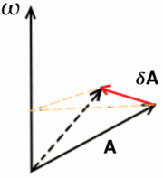
A couple of posts back, when dealing with rotation, I wondered how I could model the property of angular momentum. Inertial momentum is easy enough to represent with a speed vector which you add to the entity's position every frame. Velocity shares several characteristics with rotation, surprisingly. In physics angular velocity is also represented with a vector, with the direction determining the axis of rotation and the length the angular speed. I figured this was, after all, everything I needed. It would make sense then to try to use it.
It wasn't too much work to add a vector to the entity object, and modify the code so that pressing the rotation keys would add to this vector. The rather clever bit, I think, is that I store the vector in world coordinates. By keeping track of the frame of reference for my objects I can easily convert between local and world coordinates. This is important because I add rotation along the three local axis, but convert the addition to global coordinates before adding them to my rotation vector.
Then in the update logic I rotate along the vector's axis by an amount determined by its length. One thing to keep in mind though is that to make the rotation look realistic, I have to center models on their center of mass. Easy enough on regular geometric shapes, but I'll have to figure out something for complex models, or models with moving parts.
The demo for this is available for download: Framework-0.0.4r
It's fun to mess around with. There's a weird effect that happens when you spin up significantly, and the refresh rate starts to match up with the turning speed and the sphere appears to slow down or rotate backwards.
You can also hopelessly lose control of the thing if you mix too much spin in different directions. It should be possible to recover from the perspective of someone inside, since you can easily break down the spin one axis at a time. That's something for the next update, though.
 |
| The farther away from the axis of rotation, the greater the change in position. |
Then in the update logic I rotate along the vector's axis by an amount determined by its length. One thing to keep in mind though is that to make the rotation look realistic, I have to center models on their center of mass. Easy enough on regular geometric shapes, but I'll have to figure out something for complex models, or models with moving parts.
The demo for this is available for download: Framework-0.0.4r
It's fun to mess around with. There's a weird effect that happens when you spin up significantly, and the refresh rate starts to match up with the turning speed and the sphere appears to slow down or rotate backwards.
You can also hopelessly lose control of the thing if you mix too much spin in different directions. It should be possible to recover from the perspective of someone inside, since you can easily break down the spin one axis at a time. That's something for the next update, though.
Thursday, September 1, 2011
Modeling a sphere, the new way
Back when I began this blog, almost a year ago, I set a goal for myself of drawing a sphere. Back then I didn't know about the fixed pipeline, and how it had been replaced by shaders and a more flexible approach. I was pretty much learning as I went, and I was just starting out.
Now on my 50th post, I have a bit more experience under my belt, and it's interesting to see how far I've come and how I've changed the approach for doing exactly the same. It hasn't been easy or smooth, I've had to start over three or four times, but through it all I've progressed.
Last year my approach had used the fixed pipeline, and I was sending triangle strips to be rendered, one slice of the sphere at a time. This time, what I've done is create a set of vertices, and build the triangles by connecting the dots. By creating a vertex buffer array, the information is stored in the video memory meaning I don't have to send a load of data to the graphics card each frame.
Fair warning, there's a bit of geometry ahead. I'll try to be clear.
I want to find the positions of the points at the intersections, which are the ones I'll use as vertices for my triangles. My approach is to loop through the grid, finding the spherical coordinates (radius, angle theta from the horizontal plane and angle phi around the axis) for each point and translating them to Cartesian coordinates (x, y, z).
To make matters easier I'll create a sphere with radius 1. If I want to use a larger sphere later, I can just scale the model accordingly. I'm also going to be working out the normals for each point. Since this is a sphere with radius 1, though, the normals will be the same as the coordinates.
Working out the spherical coordinates of the points is simple enough. Theta can vary between 0 and pi, and phi can vary between 0 and 2*pi. For a sphere of a given resolution, determined by the number of cuts and slices I use, I can determine the variation between grid points along each coordinate. With three cuts for example, the theta values would be 0 (for the north pole), pi/4 (45°), pi/2(90°, ecuator), 3pi/4 (135°) and pi (for the south pole).
Then it's just a matter of looping through all the possible values for each spherical coordinate, and translating to Cartesian, which is a simple trigonometry operation.
I now have a list with all the points in the sphere. The next thing I need to do is to create a list of indices, telling me which points make each triangle. If I had the four points
I could use the two triangles define by the points 1,2,4 and 2,3,4 to build a square, for example. With the sphere it's the same. Knowing how I traverse the sphere in the first place, I can determine which points build the triangles on the surface. It's important though to consider that the polar caps of the model behave differently than the main body, but that special case is simple enough to handle.
After I've stored all this information in arrays, I need to feed it to the video card. I build a vertex buffer array, which stores information about what buffer objects to use, and several vertex buffer objects to actually store the information. For each point I'm storing it's position, normal, color, and texture coordinates. Add the index array for telling the card how to group them into triangles, and I need to use five buffers. On the plus side, that's a whole lot of information I no longer need to worry about. When I next wish to draw the sphere, I simply bind the vertex buffer array and draw it.
The result is visible in the demo for Framewrok-0.0.3r, where I changed the old single triangle model for a fairly detailed sphere.
Now on my 50th post, I have a bit more experience under my belt, and it's interesting to see how far I've come and how I've changed the approach for doing exactly the same. It hasn't been easy or smooth, I've had to start over three or four times, but through it all I've progressed.
Last year my approach had used the fixed pipeline, and I was sending triangle strips to be rendered, one slice of the sphere at a time. This time, what I've done is create a set of vertices, and build the triangles by connecting the dots. By creating a vertex buffer array, the information is stored in the video memory meaning I don't have to send a load of data to the graphics card each frame.
Same as before, I'm cutting the sphere like a globe, with parallels running east to west and meridians running north to south.
 |
| In spherical coordinates, parallels correspond to theta values and meridians to phi values. |
I want to find the positions of the points at the intersections, which are the ones I'll use as vertices for my triangles. My approach is to loop through the grid, finding the spherical coordinates (radius, angle theta from the horizontal plane and angle phi around the axis) for each point and translating them to Cartesian coordinates (x, y, z).
To make matters easier I'll create a sphere with radius 1. If I want to use a larger sphere later, I can just scale the model accordingly. I'm also going to be working out the normals for each point. Since this is a sphere with radius 1, though, the normals will be the same as the coordinates.
Working out the spherical coordinates of the points is simple enough. Theta can vary between 0 and pi, and phi can vary between 0 and 2*pi. For a sphere of a given resolution, determined by the number of cuts and slices I use, I can determine the variation between grid points along each coordinate. With three cuts for example, the theta values would be 0 (for the north pole), pi/4 (45°), pi/2(90°, ecuator), 3pi/4 (135°) and pi (for the south pole).
Then it's just a matter of looping through all the possible values for each spherical coordinate, and translating to Cartesian, which is a simple trigonometry operation.
I now have a list with all the points in the sphere. The next thing I need to do is to create a list of indices, telling me which points make each triangle. If I had the four points
1 ( 0, 1, 0)
2 (-1, 0, 0)
3 ( 0,-1, 0)
4 ( 1, 0, 0)
I could use the two triangles define by the points 1,2,4 and 2,3,4 to build a square, for example. With the sphere it's the same. Knowing how I traverse the sphere in the first place, I can determine which points build the triangles on the surface. It's important though to consider that the polar caps of the model behave differently than the main body, but that special case is simple enough to handle.
After I've stored all this information in arrays, I need to feed it to the video card. I build a vertex buffer array, which stores information about what buffer objects to use, and several vertex buffer objects to actually store the information. For each point I'm storing it's position, normal, color, and texture coordinates. Add the index array for telling the card how to group them into triangles, and I need to use five buffers. On the plus side, that's a whole lot of information I no longer need to worry about. When I next wish to draw the sphere, I simply bind the vertex buffer array and draw it.
The result is visible in the demo for Framewrok-0.0.3r, where I changed the old single triangle model for a fairly detailed sphere.
Wednesday, August 31, 2011
Rotation
With translation out of the way, I moved on to something more complicated. Rotation.
The last time I went about it, I tried it with quaternions. It was time consuming and I'm not entirely sure how it even ended up working. Euler angles are even worse. Vectors and matrices, however, seem more suited to solve the problem and play nice with OpenGL. And since the GLTools library I'm using already handles that, I really only need to wrap a few calls in my entities to get it working.
As I mentioned in my previous post, I have a reference frame determined by three vectors and a position. This makes local rotations simple. If I want to roll along the length of the model, I rotate around the forward vector. If I want to change the pitch of the model, I rotate around the right vector. And if I want to turn to either side, I rotate around the up vector.
I do the same basic set up as I did for translation, except my keys now affect rotation. I tie each pair of keys to a fixed rotation around each of my local axis, so that as long as I hold a key the model rotates and on release it stops rotating.
This gets the model turning about, and to spice things up I decide to give it the ability to accelerate. I first create a velocity vector, initially set to 0 so the body is at rest. Then, when I accelerate, I add to the vector a speed increment in the forward direction. When it comes time to update my entity's position, I add the velocity vector to it's position and done. This models newtonian movement well enough; velocity is constant unless I accelerate in a given direction. If I want to stop, I have to accelerate in the opposite direction to my movement.
I can rotate around independently of my direction of movement because I store the velocity vector in global coordinates. I could easily work out the vector in local coordinates as well, and it would provide a vector that moves around as I rotate the ship.
The result is Framework-0.0.2r.
What is missing, however, is that rotation should also be continuous unless I stop it. I'm modeling conservation of momentum, but not of angular momentum. I would need to store another vector, much like the velocity vector, which is affected by what kind of rotation I attempt. Unfortunately I'm not 100% sure on the physics involved here. Ideally I could just add vectors, same as with speed. The angle of rotation would be determined by the magnitude of the vector, while the axis of rotation would be the direction of the vector. That feels about right, and I should have it set up for Framework-0.0.4r.
Next up, I reworked my sphere building algorithms from the very beginnings of this blog. I used to use triangle strips, but together with the fixed pipeline that's obsolete. Vertex lists and indices is where it's at now.
The last time I went about it, I tried it with quaternions. It was time consuming and I'm not entirely sure how it even ended up working. Euler angles are even worse. Vectors and matrices, however, seem more suited to solve the problem and play nice with OpenGL. And since the GLTools library I'm using already handles that, I really only need to wrap a few calls in my entities to get it working.
As I mentioned in my previous post, I have a reference frame determined by three vectors and a position. This makes local rotations simple. If I want to roll along the length of the model, I rotate around the forward vector. If I want to change the pitch of the model, I rotate around the right vector. And if I want to turn to either side, I rotate around the up vector.
I do the same basic set up as I did for translation, except my keys now affect rotation. I tie each pair of keys to a fixed rotation around each of my local axis, so that as long as I hold a key the model rotates and on release it stops rotating.
This gets the model turning about, and to spice things up I decide to give it the ability to accelerate. I first create a velocity vector, initially set to 0 so the body is at rest. Then, when I accelerate, I add to the vector a speed increment in the forward direction. When it comes time to update my entity's position, I add the velocity vector to it's position and done. This models newtonian movement well enough; velocity is constant unless I accelerate in a given direction. If I want to stop, I have to accelerate in the opposite direction to my movement.
I can rotate around independently of my direction of movement because I store the velocity vector in global coordinates. I could easily work out the vector in local coordinates as well, and it would provide a vector that moves around as I rotate the ship.
The result is Framework-0.0.2r.
What is missing, however, is that rotation should also be continuous unless I stop it. I'm modeling conservation of momentum, but not of angular momentum. I would need to store another vector, much like the velocity vector, which is affected by what kind of rotation I attempt. Unfortunately I'm not 100% sure on the physics involved here. Ideally I could just add vectors, same as with speed. The angle of rotation would be determined by the magnitude of the vector, while the axis of rotation would be the direction of the vector. That feels about right, and I should have it set up for Framework-0.0.4r.
Next up, I reworked my sphere building algorithms from the very beginnings of this blog. I used to use triangle strips, but together with the fixed pipeline that's obsolete. Vertex lists and indices is where it's at now.
Progress!
Lots to talk about. I haven't been posting here as often as I'd like, but I have managed to get quite a bit of work done.
Let's see, last time, I had a triangle on the screen. And I wanted to make it interactive. The first thing I did was create a few methods in my entity object that would modify the entity's frame of reference.The frame of reference describes the position and orientation of something in space, and helps translate between local and global coordinates.
Local coordinates are coordinates from the object's point of view, while global coordinates are the coordinate system of the world the object is in. For ease of reading, I'll denote local coordinates as (x,y,z)l, and global coordinates as (x,y,z)g.
From the object's perspective (meaning in local coordinates), all points are static. It's center is always at (0,0,0)l, and the axis are always (1,0,0)l,(0,1,0)l and (0,0,1)l. A point at (1,1,1)l is always at (1,1,1)l.
The same point in global coordinates, however, depends on the position and orientation of the object in the world. When the object sits still at the global origin, both coordinate systems match up. If the object moves 1 unit forward, so the local origin now sits at (1,0,0)g, then the point that is (1,1,1)l is actually (2,1,1)g.
We can define a frame of reference as an origin (the position in global coordinates), a forward vector (in global coordinates) and an up vector (in global coordinates). From the cross product of these two vectors I can get the right vector, and these three determine the orientation of the local coordinate axis.
That's the difficult part out of the way, then.
I started with translation, which was easy enough. In order to advance 'forwards', I need to advance along the object's forward vector. To do this, I simply add the forward vector times a speed factor to the object's origin, and tie this to a key input. I can do the same with the up and right vectors, and the result is that the object will move around the screen when you press a key.
Quite surprisingly, I did it, and it worked! I was on a roll, so I even modified the shader so it would accept the color of a given point and shade the resulting triangle with the value of each point.
I'll put up a few screenshots later. I'm also thinking I'll put the demo here just in case. If I can work out how to do it.
And I did, thanks to google. Now you too can get Framework 0.0.1r! You only need 7zip to uncompress it, and it comes ready to run.
Let's see, last time, I had a triangle on the screen. And I wanted to make it interactive. The first thing I did was create a few methods in my entity object that would modify the entity's frame of reference.The frame of reference describes the position and orientation of something in space, and helps translate between local and global coordinates.
Local coordinates are coordinates from the object's point of view, while global coordinates are the coordinate system of the world the object is in. For ease of reading, I'll denote local coordinates as (x,y,z)l, and global coordinates as (x,y,z)g.
From the object's perspective (meaning in local coordinates), all points are static. It's center is always at (0,0,0)l, and the axis are always (1,0,0)l,(0,1,0)l and (0,0,1)l. A point at (1,1,1)l is always at (1,1,1)l.
The same point in global coordinates, however, depends on the position and orientation of the object in the world. When the object sits still at the global origin, both coordinate systems match up. If the object moves 1 unit forward, so the local origin now sits at (1,0,0)g, then the point that is (1,1,1)l is actually (2,1,1)g.
We can define a frame of reference as an origin (the position in global coordinates), a forward vector (in global coordinates) and an up vector (in global coordinates). From the cross product of these two vectors I can get the right vector, and these three determine the orientation of the local coordinate axis.
That's the difficult part out of the way, then.
I started with translation, which was easy enough. In order to advance 'forwards', I need to advance along the object's forward vector. To do this, I simply add the forward vector times a speed factor to the object's origin, and tie this to a key input. I can do the same with the up and right vectors, and the result is that the object will move around the screen when you press a key.
Quite surprisingly, I did it, and it worked! I was on a roll, so I even modified the shader so it would accept the color of a given point and shade the resulting triangle with the value of each point.
I'll put up a few screenshots later. I'm also thinking I'll put the demo here just in case. If I can work out how to do it.
And I did, thanks to google. Now you too can get Framework 0.0.1r! You only need 7zip to uncompress it, and it comes ready to run.
Subscribe to:
Posts (Atom)