So last time, I had managed to add some code to create a height-map from a simplex noise function, using the space coordinates as input and getting a pseudo-random number between -1 and 1 as the output. For now I'm just coloring the vertices, black for lowest value and white for highest, but eventually I'd use the values to distort the sphere.
The only problem was that the noise function used a shuffled array to create the pattern of noise, so in order to create new patterns I had to reshuffle that array. Reshuffling the array presented a few problems, mostly caused by my reliance on the STL's rand() function, which is really quite terrible. As a result I had to search for a better function that could do the job I needed.
I eventually found an excellent paper on pseudo random number generators, by David Jones. I settled for the JLKISS64 generator, and after altering it to fit the framework I managed to create multiple height maps on demand. The problem, then, was how to display them.
Currently, my method for displaying models is to create a Vertex Buffer Array for each model, and a custom transform for each object. The different spheres where really all the same array with different matrices applied. But the height map was created as an additional coloring at each vertex, meaning I had to create new Arrays that still used the same buffers for vertex position, normal and color, but different heights.
This was fairly straightforward, thankfully. Essentially, the process involved the same steps as creating a vertex array from scratch, but skipping the buffer step, since the information had already been loaded to the video card.
In short order I had the new code running, and the space that was once filled with the same patterned spheres now had unique marbles floating all about.
Next up, I'm going to be trying to get text into the program, create a console of sorts.
Showing posts with label Coordinates. Show all posts
Showing posts with label Coordinates. Show all posts
Monday, January 16, 2012


Monday, November 14, 2011
Giving shape to the world
I finally have an interesting playground to experiment in, so it's about time I focused on what I wanted to do in the first place. The main drive behind this project was procedural content, making use of algorithms to populate the world with variety instead of a fixed number of precomputed models. I've already been doing that, in fact. The distribution of spheres in the demo, for example, and their size, is all deterministically decided by the program at run time.
All I do is decide how many spheres I want, what the range of sizes should be, and the volume of space to use. The program then fills the space. Because the starting conditions are always the same, the program always builds the same scene. I could easily create a different distribution by changing the seed or any of the parameters. I want to go further, though. Right now, all these spheres are kind of boring. And not very asteroid like. To change this, I'll deform the spheres to create more interesting shapes.
My initial plan is to assign each sphere a height map. I'll then use the height map to raise or lower away from the center of the sphere each vertex. One difficulty I expect is how to adjust the normals as the terrain is reshaped, but I'll figure something out. On the height map end, I'll use the simplex noise algorithms I've talked about before to give each asteroid a distinct look. By seeding each asteroid with a distinct value, I ensure they'll all be unique.
For the height map, I only need it to match one pixel to a vertex. This way I can send the value to the vertex shader as an attribute. I already created the spheres using a gridlike pattern, so I can use the uv coordinates of each pixel for this purpose. This does mean that there will be more detail near the poles that along the equator, but because my source is going to be a 3d density function it should not result in any obvious distortions. The output will go into a Vertex Buffer Object, which will be fed to the video card and called when drawing.
Normally, height maps add a height to points on a grid, which is level with either the XZ or XY planes, meaning Z or Y is treated as height, and that value is replaced with the value of the height map. However, I have a sphere. On a sphere, height is defined as the distance from the center. To apply the height map to a sphere, I have to work a bit more.
The values I have will fall between -1 and 1. If I do straight multiplication of the surface point by the value, I'd have a mess. Instead, what I do is decide what I want the range of heights to be. If I want the highest points to jut out three times the radius of the sphere, for example, and the deepest valleys to reach half way to the center of the sphere, that gives me a range of (3 - 0.5 ) = 2.5 radius. The half point (where the height map is 0) would be 1.25 radius, so I could get the position of every point as ( (1+height)*1.25 + 0.5) * position.
The other complex bit is recalculating the normals. By changing the shape of the sphere, the surface normals all change as well and that impacts the light on each point. If I don't get them right, the lighting will look decidedly odd.
That's getting ahead of me a bit. First I need to be sure I can produce the information and get it into the shader. I had to add an extra attribute to the Model class to do it, but after a few short tweaks I got it up and running. What I'm doing right now is using the height value of each point as a color value, with -1 being black and 1 being white. So higher areas will look brighter.
It's working, and I'm pretty happy about that. I'm now struggling with an odd problem; when running the project from a pendrive it works, but copying the project to the hard drive and running it there doesn't. Fixing that is probably going to give me enough for another post itself.
All I do is decide how many spheres I want, what the range of sizes should be, and the volume of space to use. The program then fills the space. Because the starting conditions are always the same, the program always builds the same scene. I could easily create a different distribution by changing the seed or any of the parameters. I want to go further, though. Right now, all these spheres are kind of boring. And not very asteroid like. To change this, I'll deform the spheres to create more interesting shapes.
My initial plan is to assign each sphere a height map. I'll then use the height map to raise or lower away from the center of the sphere each vertex. One difficulty I expect is how to adjust the normals as the terrain is reshaped, but I'll figure something out. On the height map end, I'll use the simplex noise algorithms I've talked about before to give each asteroid a distinct look. By seeding each asteroid with a distinct value, I ensure they'll all be unique.
 |
| A sample of simplex noise |
For the height map, I only need it to match one pixel to a vertex. This way I can send the value to the vertex shader as an attribute. I already created the spheres using a gridlike pattern, so I can use the uv coordinates of each pixel for this purpose. This does mean that there will be more detail near the poles that along the equator, but because my source is going to be a 3d density function it should not result in any obvious distortions. The output will go into a Vertex Buffer Object, which will be fed to the video card and called when drawing.
Normally, height maps add a height to points on a grid, which is level with either the XZ or XY planes, meaning Z or Y is treated as height, and that value is replaced with the value of the height map. However, I have a sphere. On a sphere, height is defined as the distance from the center. To apply the height map to a sphere, I have to work a bit more.
The values I have will fall between -1 and 1. If I do straight multiplication of the surface point by the value, I'd have a mess. Instead, what I do is decide what I want the range of heights to be. If I want the highest points to jut out three times the radius of the sphere, for example, and the deepest valleys to reach half way to the center of the sphere, that gives me a range of (3 - 0.5 ) = 2.5 radius. The half point (where the height map is 0) would be 1.25 radius, so I could get the position of every point as ( (1+height)*1.25 + 0.5) * position.
The other complex bit is recalculating the normals. By changing the shape of the sphere, the surface normals all change as well and that impacts the light on each point. If I don't get them right, the lighting will look decidedly odd.
That's getting ahead of me a bit. First I need to be sure I can produce the information and get it into the shader. I had to add an extra attribute to the Model class to do it, but after a few short tweaks I got it up and running. What I'm doing right now is using the height value of each point as a color value, with -1 being black and 1 being white. So higher areas will look brighter.
 |
| Looks nicer than blue with red and green dots. |
It's working, and I'm pretty happy about that. I'm now struggling with an odd problem; when running the project from a pendrive it works, but copying the project to the hard drive and running it there doesn't. Fixing that is probably going to give me enough for another post itself.
Saturday, September 3, 2011
Angular Momentum
A couple of posts back, when dealing with rotation, I wondered how I could model the property of angular momentum. Inertial momentum is easy enough to represent with a speed vector which you add to the entity's position every frame. Velocity shares several characteristics with rotation, surprisingly. In physics angular velocity is also represented with a vector, with the direction determining the axis of rotation and the length the angular speed. I figured this was, after all, everything I needed. It would make sense then to try to use it.
It wasn't too much work to add a vector to the entity object, and modify the code so that pressing the rotation keys would add to this vector. The rather clever bit, I think, is that I store the vector in world coordinates. By keeping track of the frame of reference for my objects I can easily convert between local and world coordinates. This is important because I add rotation along the three local axis, but convert the addition to global coordinates before adding them to my rotation vector.
Then in the update logic I rotate along the vector's axis by an amount determined by its length. One thing to keep in mind though is that to make the rotation look realistic, I have to center models on their center of mass. Easy enough on regular geometric shapes, but I'll have to figure out something for complex models, or models with moving parts.
The demo for this is available for download: Framework-0.0.4r
It's fun to mess around with. There's a weird effect that happens when you spin up significantly, and the refresh rate starts to match up with the turning speed and the sphere appears to slow down or rotate backwards.
You can also hopelessly lose control of the thing if you mix too much spin in different directions. It should be possible to recover from the perspective of someone inside, since you can easily break down the spin one axis at a time. That's something for the next update, though.
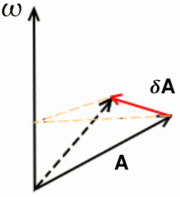 |
| The farther away from the axis of rotation, the greater the change in position. |
Then in the update logic I rotate along the vector's axis by an amount determined by its length. One thing to keep in mind though is that to make the rotation look realistic, I have to center models on their center of mass. Easy enough on regular geometric shapes, but I'll have to figure out something for complex models, or models with moving parts.
The demo for this is available for download: Framework-0.0.4r
It's fun to mess around with. There's a weird effect that happens when you spin up significantly, and the refresh rate starts to match up with the turning speed and the sphere appears to slow down or rotate backwards.
You can also hopelessly lose control of the thing if you mix too much spin in different directions. It should be possible to recover from the perspective of someone inside, since you can easily break down the spin one axis at a time. That's something for the next update, though.
Thursday, September 1, 2011
Modeling a sphere, the new way
Back when I began this blog, almost a year ago, I set a goal for myself of drawing a sphere. Back then I didn't know about the fixed pipeline, and how it had been replaced by shaders and a more flexible approach. I was pretty much learning as I went, and I was just starting out.
Now on my 50th post, I have a bit more experience under my belt, and it's interesting to see how far I've come and how I've changed the approach for doing exactly the same. It hasn't been easy or smooth, I've had to start over three or four times, but through it all I've progressed.
Last year my approach had used the fixed pipeline, and I was sending triangle strips to be rendered, one slice of the sphere at a time. This time, what I've done is create a set of vertices, and build the triangles by connecting the dots. By creating a vertex buffer array, the information is stored in the video memory meaning I don't have to send a load of data to the graphics card each frame.
Fair warning, there's a bit of geometry ahead. I'll try to be clear.
I want to find the positions of the points at the intersections, which are the ones I'll use as vertices for my triangles. My approach is to loop through the grid, finding the spherical coordinates (radius, angle theta from the horizontal plane and angle phi around the axis) for each point and translating them to Cartesian coordinates (x, y, z).
To make matters easier I'll create a sphere with radius 1. If I want to use a larger sphere later, I can just scale the model accordingly. I'm also going to be working out the normals for each point. Since this is a sphere with radius 1, though, the normals will be the same as the coordinates.
Working out the spherical coordinates of the points is simple enough. Theta can vary between 0 and pi, and phi can vary between 0 and 2*pi. For a sphere of a given resolution, determined by the number of cuts and slices I use, I can determine the variation between grid points along each coordinate. With three cuts for example, the theta values would be 0 (for the north pole), pi/4 (45°), pi/2(90°, ecuator), 3pi/4 (135°) and pi (for the south pole).
Then it's just a matter of looping through all the possible values for each spherical coordinate, and translating to Cartesian, which is a simple trigonometry operation.
I now have a list with all the points in the sphere. The next thing I need to do is to create a list of indices, telling me which points make each triangle. If I had the four points
I could use the two triangles define by the points 1,2,4 and 2,3,4 to build a square, for example. With the sphere it's the same. Knowing how I traverse the sphere in the first place, I can determine which points build the triangles on the surface. It's important though to consider that the polar caps of the model behave differently than the main body, but that special case is simple enough to handle.
After I've stored all this information in arrays, I need to feed it to the video card. I build a vertex buffer array, which stores information about what buffer objects to use, and several vertex buffer objects to actually store the information. For each point I'm storing it's position, normal, color, and texture coordinates. Add the index array for telling the card how to group them into triangles, and I need to use five buffers. On the plus side, that's a whole lot of information I no longer need to worry about. When I next wish to draw the sphere, I simply bind the vertex buffer array and draw it.
The result is visible in the demo for Framewrok-0.0.3r, where I changed the old single triangle model for a fairly detailed sphere.
Now on my 50th post, I have a bit more experience under my belt, and it's interesting to see how far I've come and how I've changed the approach for doing exactly the same. It hasn't been easy or smooth, I've had to start over three or four times, but through it all I've progressed.
Last year my approach had used the fixed pipeline, and I was sending triangle strips to be rendered, one slice of the sphere at a time. This time, what I've done is create a set of vertices, and build the triangles by connecting the dots. By creating a vertex buffer array, the information is stored in the video memory meaning I don't have to send a load of data to the graphics card each frame.
Same as before, I'm cutting the sphere like a globe, with parallels running east to west and meridians running north to south.
 |
| In spherical coordinates, parallels correspond to theta values and meridians to phi values. |
I want to find the positions of the points at the intersections, which are the ones I'll use as vertices for my triangles. My approach is to loop through the grid, finding the spherical coordinates (radius, angle theta from the horizontal plane and angle phi around the axis) for each point and translating them to Cartesian coordinates (x, y, z).
To make matters easier I'll create a sphere with radius 1. If I want to use a larger sphere later, I can just scale the model accordingly. I'm also going to be working out the normals for each point. Since this is a sphere with radius 1, though, the normals will be the same as the coordinates.
Working out the spherical coordinates of the points is simple enough. Theta can vary between 0 and pi, and phi can vary between 0 and 2*pi. For a sphere of a given resolution, determined by the number of cuts and slices I use, I can determine the variation between grid points along each coordinate. With three cuts for example, the theta values would be 0 (for the north pole), pi/4 (45°), pi/2(90°, ecuator), 3pi/4 (135°) and pi (for the south pole).
Then it's just a matter of looping through all the possible values for each spherical coordinate, and translating to Cartesian, which is a simple trigonometry operation.
I now have a list with all the points in the sphere. The next thing I need to do is to create a list of indices, telling me which points make each triangle. If I had the four points
1 ( 0, 1, 0)
2 (-1, 0, 0)
3 ( 0,-1, 0)
4 ( 1, 0, 0)
I could use the two triangles define by the points 1,2,4 and 2,3,4 to build a square, for example. With the sphere it's the same. Knowing how I traverse the sphere in the first place, I can determine which points build the triangles on the surface. It's important though to consider that the polar caps of the model behave differently than the main body, but that special case is simple enough to handle.
After I've stored all this information in arrays, I need to feed it to the video card. I build a vertex buffer array, which stores information about what buffer objects to use, and several vertex buffer objects to actually store the information. For each point I'm storing it's position, normal, color, and texture coordinates. Add the index array for telling the card how to group them into triangles, and I need to use five buffers. On the plus side, that's a whole lot of information I no longer need to worry about. When I next wish to draw the sphere, I simply bind the vertex buffer array and draw it.
The result is visible in the demo for Framewrok-0.0.3r, where I changed the old single triangle model for a fairly detailed sphere.
Wednesday, August 31, 2011
Progress!
Lots to talk about. I haven't been posting here as often as I'd like, but I have managed to get quite a bit of work done.
Let's see, last time, I had a triangle on the screen. And I wanted to make it interactive. The first thing I did was create a few methods in my entity object that would modify the entity's frame of reference.The frame of reference describes the position and orientation of something in space, and helps translate between local and global coordinates.
Local coordinates are coordinates from the object's point of view, while global coordinates are the coordinate system of the world the object is in. For ease of reading, I'll denote local coordinates as (x,y,z)l, and global coordinates as (x,y,z)g.
From the object's perspective (meaning in local coordinates), all points are static. It's center is always at (0,0,0)l, and the axis are always (1,0,0)l,(0,1,0)l and (0,0,1)l. A point at (1,1,1)l is always at (1,1,1)l.
The same point in global coordinates, however, depends on the position and orientation of the object in the world. When the object sits still at the global origin, both coordinate systems match up. If the object moves 1 unit forward, so the local origin now sits at (1,0,0)g, then the point that is (1,1,1)l is actually (2,1,1)g.
We can define a frame of reference as an origin (the position in global coordinates), a forward vector (in global coordinates) and an up vector (in global coordinates). From the cross product of these two vectors I can get the right vector, and these three determine the orientation of the local coordinate axis.
That's the difficult part out of the way, then.
I started with translation, which was easy enough. In order to advance 'forwards', I need to advance along the object's forward vector. To do this, I simply add the forward vector times a speed factor to the object's origin, and tie this to a key input. I can do the same with the up and right vectors, and the result is that the object will move around the screen when you press a key.
Quite surprisingly, I did it, and it worked! I was on a roll, so I even modified the shader so it would accept the color of a given point and shade the resulting triangle with the value of each point.
I'll put up a few screenshots later. I'm also thinking I'll put the demo here just in case. If I can work out how to do it.
And I did, thanks to google. Now you too can get Framework 0.0.1r! You only need 7zip to uncompress it, and it comes ready to run.
Let's see, last time, I had a triangle on the screen. And I wanted to make it interactive. The first thing I did was create a few methods in my entity object that would modify the entity's frame of reference.The frame of reference describes the position and orientation of something in space, and helps translate between local and global coordinates.
Local coordinates are coordinates from the object's point of view, while global coordinates are the coordinate system of the world the object is in. For ease of reading, I'll denote local coordinates as (x,y,z)l, and global coordinates as (x,y,z)g.
From the object's perspective (meaning in local coordinates), all points are static. It's center is always at (0,0,0)l, and the axis are always (1,0,0)l,(0,1,0)l and (0,0,1)l. A point at (1,1,1)l is always at (1,1,1)l.
The same point in global coordinates, however, depends on the position and orientation of the object in the world. When the object sits still at the global origin, both coordinate systems match up. If the object moves 1 unit forward, so the local origin now sits at (1,0,0)g, then the point that is (1,1,1)l is actually (2,1,1)g.
We can define a frame of reference as an origin (the position in global coordinates), a forward vector (in global coordinates) and an up vector (in global coordinates). From the cross product of these two vectors I can get the right vector, and these three determine the orientation of the local coordinate axis.
That's the difficult part out of the way, then.
I started with translation, which was easy enough. In order to advance 'forwards', I need to advance along the object's forward vector. To do this, I simply add the forward vector times a speed factor to the object's origin, and tie this to a key input. I can do the same with the up and right vectors, and the result is that the object will move around the screen when you press a key.
Quite surprisingly, I did it, and it worked! I was on a roll, so I even modified the shader so it would accept the color of a given point and shade the resulting triangle with the value of each point.
I'll put up a few screenshots later. I'm also thinking I'll put the demo here just in case. If I can work out how to do it.
And I did, thanks to google. Now you too can get Framework 0.0.1r! You only need 7zip to uncompress it, and it comes ready to run.
Subscribe to:
Posts (Atom)